40 Series Sundstrand
We service 40 Series Sundstrand hydrostatic pumps.
Excellent Sundstrand 40 Series pump repair.
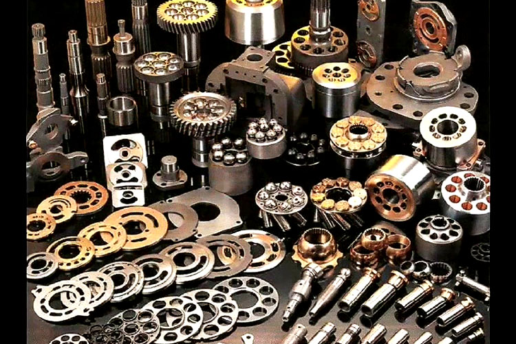
40 series Sundstrand Hydrostatic pumps before being Hydrostatic rebuilt, Sundstrand remanufactured, and Sundstrand Hydrostatic pump repaired
These 40 series Sundstrand pumps have just come in to the Hydrostatic Transmission Service , LLC hydrostatic pump repair shop to be remanufactured.
They will be taken apart, cleaned and all of the internal components checked. Where needed the Sundstrand rotating group consisting of Sundstrand pistons, Sundstrand cylinder block, Sundstrand ball guide, Sundstrand positive hold-down , and Sundstrand plates will be replaced with new Sundstrand hydrostatic parts. After the repair the 40 series Sundstrand hydrostatic pumps or Hydrostatic Transmissions as normally called will be tested on a special designed test bench, used to test Sundstrand Hydrostatic pumps, motors, transmissions, drives, equipment and parts. And calibrated back to Sundstrand Hydrostatic parts factory specs. The Sundstrand Hydrostatic pumps are then cleaned and boxed for shipment to the end user. All of Hydrostatic Transmission Service, LLC remanufactured pumps carry a one year warranty.
GOT 40 SERIES HYDROSTATIC PUMP AND MOTOR QUESTIONS?
NEED 40 SERIES HYDROSTATIC PUMP AND MOTOR ANSWERS?
NEED 40 SERIES HYDROSTATIC TECHNOLOGICAL HELP?
GIVE US A CALL!
Hydrostatic Transmission Service,LLC offers lip type shaft seal on Series 40 pumps and motors The seals on these pumps and motors can be replaced with no major disassembly to the unit, although, replacement of the shaft seal calls for removal of the pump or motor from the machine. Then take out the retaining ring from the housing.
With great ease take out the seal from the housing bore. A slide hammer type puller should be used to aid in prying the seal out, otherwise the seal may become punctured if using a sharp instrument. Restraint should be taken so the housing bore or shaft doesn’t become damaged. The seal is not reusable after it’s removal.
Before installing the new seal, look the sealing areas over on the shaft for rust, wear, or contamination. Also if it calls for it polish the sealing area.
The key end of shaft needs to be wrapped with lightweight plastic to avoid damage to the seal lip during installation. Grease the inside thickness of the new seal with petroleum jelly.
Slide the new seal over the shaft and press it into the housing bore. Be careful not to damage seal. A seal installer tool can be made to aid in installing the seal. Dimensions for this tool are shown in the accompanying drawing.
Reinstall the seal-retaining ring.
Bypass Valve (Pump)
Unbolt the bypass valve from the housing. Look over the valve and mating seat for damage or foreign material and while this is open Hydrostatic Transmission Service,LLC recommended the O-ring and back up ring be replaced.
NOTE: Bypass valves are available with basic bypass orifices for specific applications. Hydrostatic Transmission Service,LLC recommends referring to the suitable Service Parts Manual for more information.
Then put back the bypass valve into the housing. Torque to 7to10tt.lbs. (9.5 to 13.6 Mm).
Drive shafts – a wide assortment of options are offered to suit every requirement.
High power swash plates on variable pumps and motors – oppose deflection under high load.
High potency cast iron housings –
supply greater noise damping and wall force.
High flow check valves in pumps –maintain the system at it’s highest performance with very little drop in pressure.
Charge pumps on pumps – gerotor type, numerous displacement options are accessible to curtail the needs of every purpose. Pumps are made of cast iron.
Cartridge shaft seal-allows itself to easy serviceability. Motorized face seal design makes the pumps more efficient for high speed and case pressure
Advanced cylinder barrel design –helps with high pressure and speed.
Fixed clearance slipper hold down –
Models 33 through 64 allow functions at high speed and decrease resistance. Model 76 is a ball guide unit.
Pistons – have more contact with cylinder bore ensuring low leakage.
Hydraulic servo control – offers effortless operation, along with very low control pressure.The hefty servo pistons grasp the swash plate position and offer damping.
Large case drain ports – lessen case back pressure.
- Motor Performance
Model (unit Number)
33
39
46
54
64
76
Displacement
in’/rev
3.32
3.89
4.60
5.44
6.44
7.62
cm’/rev
54,4
63,7
75,3
89,1
105,5
124,8
Highest Shaft Speed
RPM
@ 18°
4510*
4160
4160
3720
3720
2775
RPM
@ 10°
5380-
5380-
5380″
4810-
481(T
3425-
Highest Amoutn of Torque t
Ib-in
2959
3511
4149
4916
5807
6911
Nm
334
397
469
556
656
781
The highest swash plate angle on model 33 motors is 15.5°.
- These shaft speeds need the highest amount of charge pressure release: 340 psi [23 bar] pump and 280 psi [19 bar] motor.
Fluids Hydraulic fluids used with Sundstrand-Sauer Hydrostatic Transmission products should be selected with assistance from a reputable supplier, (Hydrostatic Transmission),following the guidelines presented in the “Fluid Quality Requirements” bulletin, BLN-9887. Start-Up Procedure It is important to follow the procedures for a new Series 40 – Sundstrand Sauer Hydrostatic Transmission for installing or restarting an installation on a pump or motor that has been detached from a Sundstrand system. CAUTION Quick Tip- the vehicle/machine is to be disabled uplift the wheels off the ground and turn the machine off. Then it is safe to proceed to performing the process in order to prevent injury to the mechanic or anyone standing by. Therefore, take the crucial safety precautions before moving the vehicle/machine. Before installing the pump and/or motor, examine the units for damage incurred during shipping and handling. Make sure all the system components are clean preceding filling it with fluid. (reservoir, hoses, valves, fittings, heat exchanger). Fill the reservoir with suggested hydraulic fluid, which should be passed through a 10-micron (no bypass) filter prior to the ingoing fluid to the reservoir. Fluids that are containing foreign particle will cause damage to the components, and may be the reason in unexpected vehicle/machine movement. The inlet line that leads from the reservoir to the pump should be filled before start up and make sure the inlet lines have tight fittings, free of restrictions and air leaks. Very important: to fill the pump and/or motor housing with clean hydraulic fluid before the start up. Fill the housing up with filtered oil in the upper case drain port. It is suggested to Install a 0 to 500 PSI (35 BAR) pressure gauge to observe the charge pressure during start-up. It is suggested by Hydrostatic Transmssion,LLC that the outer control input signal (connection for MDC, hydraulic lines for HOC and electrical connections for EDC) be detached at the pump control until initial start-up is satisfactory. This allows the pump to remain in neutral position. “Nudge” or slowly turn prime mover pending charge pressure starts to rise. Running the prime mover at the lowest possible RPM until desired charge pressure has been reached. Bleed air from lines through the high pressure gauge ports. | |||||||||||||||||||||||||||||||||
WARNING Never start prime mover unless the pump is in neutral position,(0° swash plate angle). Always adhere to safety suggestions to ensure to prevent the machine from moving in case pump is put into motion during initial start up. Once charge pressure has been recognized, raise speed to normal operating RPM. Charge pressure should be roughly 220-PSI (15.2 BAR) minimum. If charge pressure is inaccurate, shut down and determine the cause. WARNING Not enough charge pressure will make the operator’s capability to control the vehicle/machine. Hydrostatic Transmision, LLC recommended manufactured suggestion to shut down prime mover and attach external control input signal. Start prime mover, while pump is in neutral, then at normal operating speed, gradually check for forward and reverse machine maneuver. The PSI of 220 to 240 (15.2 to 16.52) charge pressure should remain throughout forward or reverse operation. It is recommended to do this for at least five (5) minutes. Then shut down prime mover, remove gauges, and plug ports to check reservoir level and add fluid if needed. Transmission is ready for operation now. Maintenance To insure best possible service life a Sundstrand Sauer Hydrostatic Transmissions Series 40 – products, standard protection of the fluid and filter must be checked regularly. Checking the tank each day for proper fluid level is important so that, the presence of water (a cloudy to milky appearance, or water in bottom of tank), and stale fluid odor (representing extreme heat) do not occur. The manufacturer’s recommend that the fluid and filter be changed at the following increments: System with a sealed tank – 2000 hrs. System with a break in the seal tank – 500 hrs. If the fluid becomes tainted with foreign matter (dirt, water, grease, etc.) or if the fluid has been subjected to temperature levels greater than the maximum recommended, it is suggested to change the fluid more often than what is normally done. Reusing fluid is never recommended. The filter should be changed when the fluid is changed or if the filter gauge shows it is necessary to do so. | |||||||||||||||||||||||||||||||||
Series 40 – Sundstrand Sauer Standard Duty Hydrostatic Transmission
The Series 40 –Sundstrand Sauer Hydrostatic Transmission offers pumps and motors that can be helpful in extrication or combining a system to reassign and control power. When combined in a system, these units offer significant variable speed ranges between zero and maximum, in forward and reverse modes of maneuvers.
Series 40 – Sundstrand Sauer Hydrostatic Transmissions offers variable displacement pumps are condensed and up to date design, able the parallel axial piston / slipper design in combination with a tillable swash plate to vary the pump’s displacement. Reversing the manner of the tilt makes the swash plate overturn the flow of oil from the pump and thus reverses the direction of the motor output turning round.
The Series 40 – Sundstrand Sauer Hydrostatic Transmission offers variable displacement pumps and tandem pumps which in turn control a solid responsive hydro-mechanical, closed loop control system. Choices of manuals, hydraulic, or electrical displacement controls are on hand.
A charge release valve and charge test valves are incorporated in the pump end cap to control the framework and cooling oil flow for the system. The charge test valves fit in the high-pressure release valves purpose into the design.
The Series 40 –Sundstrand Sauer Hydrostatic Transmission offers variable displacement pumps, which are available with a 0.85 in3/rev (13.9 cc/rev) essential gerotor charge pump. The Series 40 – Sundstrand Sauer Hydrostatic Transmission offers tandem pumps that are accessible with a 1.40 in3/rev (22.9 cc/rev) gerotor charge pump.
The preset and changeable displacement motors include the parallel axial piston / slipper design. Preset displacement motors activate a permanent swash plate angle. The variable displacement motor has a changeable angle swash plate with a hydraulic control system, intended to give two positions of the swash plate: a maximum and minimum displacement.
We accept almost all forms of payment. If you have a payment question, give us a call.

Disclaimer: All references to OEM words are strictly for reference only and does not imply that we are an OEM distributor.