Identification
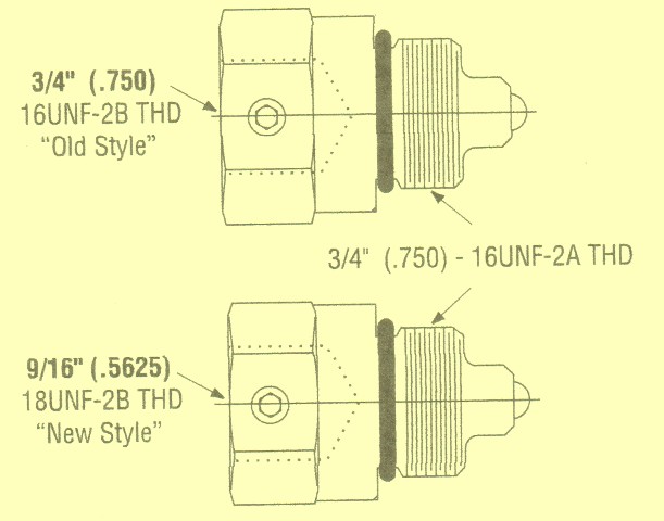
There are 2 different sized of this adapter, make note of which one you will need.
Tne newest model has a 9/16″ thread on the switch and the older one has a 3/4″ thread on the switch. So when you need to order another kit, the adapter will be in there. Also, the new models will not be interchangeable.

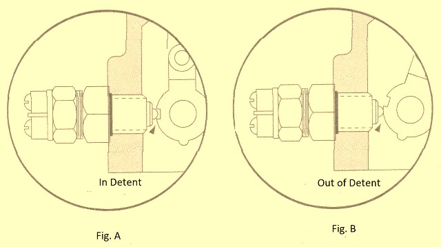
When you have the switch taken out of the adapter, put into the control assy. Tighten the adapter to no than 53 lbs. Next put in the neutral lockout switch. You will need to put some grease on the threads that is high temperature water resistant. Do this while you are rotating the control arm back and forth til you feel a catch in the arm movement. Back out of it when you feel the catch ever so slightly. You will need to make sure you take the arm out of the catch position.
Get a test light or multimeter and put the leads on the switch. If your light on the meter don’t come on right away, take the arm out til it does. Next screw the switch in just enough for the light to go off. Make this position A that have divided marks on the adapter. You will need to test your markings by using the test light. If it comes on then you know you have it put in correctly, if it doesn’t adjust the arm til it does. Screw it in just enough til the light goes off. Then you will want to mark that B, opposite the marks for A.
Now adjust the screw til it is half way the distance between B and A, tighten it up just enough. Then test the marking again. In the neutral position it should have the light on and go off when you move the control arm ever so much.
Take out your test light, put the last wiring to the neutral lockout switch, then put the servo control valve assy into the operation.


If you have any questions, please give us a call at 662-871-8403 or 800-361-0068
tupelohydraulics@gmail.com